First post, by genocho
Hi, I´m looking to replace the internal floppy drive of my Schneider Euro PC II, with a "modern" floppy, but when I extract the floppy and look at the data conector see that not is an "standard" drive.
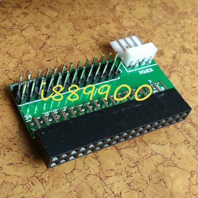
The drive is a SONY MP-F11W-S0, with 26 pin conector and no pins for power supply. I see no jumpers for select drive ds0 or ds1 (a or b), and how is a 720kb floppy drive no jumper for select high or low density.
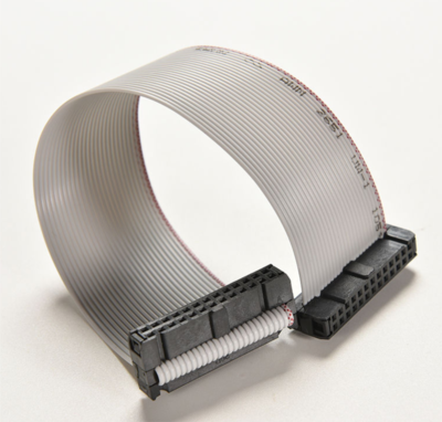
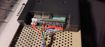
The ribbon 26 pin cable has 3 connectors, one goes to the pcb, the last is ribbon twisted (pins 3,4,5,6,7,8,9) and goes to the internal floppy drive, and in the middle there is a male db-25 for external floppy drive:
26 pin conector ------------- male db 25 --------x----26 pin conector with twisted pins 3,4,5,6,7,8,9
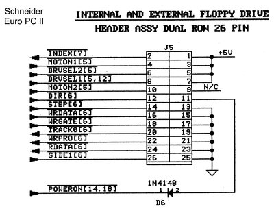
In the manual the pinout look at this:
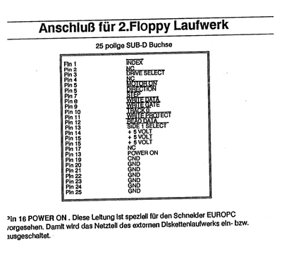
EXTERNAL EURO PC II FLOPPY PINOUT (SECOND DRIVE):
1. /INDEX
2. NC
3. /DRIVE SELECT
4. NC
5. /MOTOR ON
6. /DIRECTION
7. /STEP
8. /WRITE DATA
9. /WRITE GATE
10. /TRACK 0
11. /WRITE PROTECT
12. /READ DATA
13. /SIDE 1 SELECT
14. +5 VOLT
15. +5 VOLT
16. +5 VOLT
17. +5 VOLT
18. POWER ON
19. NC
20. GND
21. GND
22. GND
23. GND
24. GND
25. GND
26. GND
"/" all means active low:
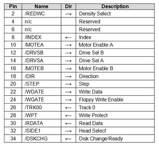
34 PIN IDC FLOPPY DRIVE:
Pin Name Dir Description
2 /REDWC --> Density Select
4 n/c Reserved
6 n/c Reserved
8 /INDEX <-- Index
10 /MOTEA --> Motor Enable A
12 /DRVSB --> Drive Sel B
14 /DRVSA --> Drive Sel A
16 /MOTEB --> Motor Enable B
18 /DIR --> Direction
20 /STEP --> Step
22 /WDATE --> Write Data
24 /WGATE --> Floppy Write Enable
26 /TRK00 <-- Track 0
28 /WPT <-- Write Protect
30 /RDATA <-- Read Data
32 /SIDE1 --> Head Select
34 /DSKCHG --> Disk Change
ALL "/" means active low
PROBLEMS I SEE:
Looking the pinout and comparing with IDC 34 PIN standard I see a lot of things differences:
- PIN 18 in euro pc is for connect or desconnect the supply of the external floppy drive, I think not is neccesary for an normal 34 pin floppy drive.
- PINS 14,15,16,17 are +5v, so I think this pinouts not be used, because 34 pin floppy drive has his own power pins.
- 34 pin idc drive have 4 pins that euro pc floppy don´t 10,12,14,16. Euro pc floppy only have 5 and 6 (motor on & direction) but not says if correspond for a or b drive, so I think can plug 5 and 6 with the corresponding 10,12 for A or 14,16 for B, but I´m not sure if this is the correct way to runs.
I think the rest of the pins are the same, and only have to solder looking at the pinouts tables.
Maybe anyone know how can make run an internal or external idc 34 pin drive
in my euro pc.
Looking in internet I see similar problems in people with korg piano´s and tandy computers, that uses 26 pin floppy drives, but the pinout not is the same at mine.
Thanks in advance and any help is welcome, perhaps anyone make something similar to this, in other machines like amiga, atari, etc,
Waiting for help,
Regards,
Genocho.